Skip to content


Gently feed in a little solder so that it melts and. One can be melting & attaching the solder to the pin header and cutting the unwanted part using the hot soldering.prepare the wire by stripping the wires ends using a wire stripper.set the iron to the solder’s temperature range;slide the heat shrink through one of the wires.
SMD How To 5 SparkFun Electronics
A mechanical connection in this case is simply taking the wire and looping it.

How to solder wires to pins. The helping hand keeps everything still while it cools. Also if you make the board several holes wider than the arduino and then drill the holes out a bit, you can thread the wires up and down and then solder which give a bit. The problem with simply soldering a wire to a metal pin is that the wire can easily break off of the pin.
Soldering wires onto header pins should only be an act of desperation. The female pins will accept the male pins, and will also slide onto 0.025 square posts. In this video i show you the tools, tips, tricks, and techniques to properly solder, from what type of.
It simply shows how to solder a wire to the pin in real time, with text running over the video. The make pins are designed to mate with the arduino uno shield connectors, and also plug into breadboards. You then have the perfect solder joint.
Take the positive lead of the wire (colored red) and hold the bare wire against the center pin of the rca connector. Learn how to solder correctly. It also helps to tin the tips of the wire.
I'm specifically using a pro mini but this could work for any arduino that came withou. The pin shown below is from vero technologies.you can wrap on both the top and bottom of the pin. Tin (coat with solder) the soldering tip first:
This would be the left side, for me. When soldering wires to connectors we are dealing with thin wires because only thin wires can be inserted into pins, and therefore we are using solder wire with a medium diameter for soldering and tinning wires. How to solder wires to pins how to solder wires to pins.
It's then just a simple job of heating up the back of the banana plug while applying the solder. Precision machined brass pins, designed. The trick is to pull the metal pins out of the plastic carrier, solder them, then push them back into the plastic.
Just use the helping hand to hold the wire in the half cylinder back of the banana plug. Wrap one or two inches of solder around the tip while the iron is cold; Press the soldering iron's tip against the wire and pin until it is hot enough so that solder pressed against the pin and wire flows around them.
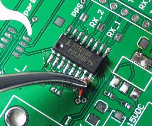
Then i take fine stranded wire and pull out one strand. Soldering small wires to very small connections (such as unused pins on qfps) first tin the connection point. Solder pins to strip board and mount the arduino upside down on the pins.
It's helps keep clean connections and makes for better heat transfer so you can do quicker solder jobs If you can find a suitable steel screen for your sheath, you can apply it to your pcb with cream solder. And allow the solder to melt.
When we bought version without pins then we need to solder them. Strip about 1/8 inch of the insulation from the wire you’d like to solder to the male header pin. I tin wire and pin, then just lay the wire right up onto the pin and solder it.
Perhaps a wire with a flat conductive circular tip that would yield nicely to, say, tape or hot glue? It's difficult to get a good connection between the pin and the board without soldering, but a press fit pin might work for you. Glue or tape it to the board (with tape under if needed for insulation) so.
The main target of this instructable is to show how to do this. Just a one two second touch should do it. Soldering a wire to a metal pin of a header is tricky.
Set the iron to the solder's temperature range; You can then solder to the strip board. Individual receptacles, designed to accept different wire sizes and mating pins, is available for mounting in cable housings per the required configurations.
Instead of soldering wires, consider crimping on male pins compatible with the headers. For tinning thicker wires you should use a solder wire with a bigger diameter. And just make sure the wire is parralel to the pins.
I also use quality flux. Solder pins to strip board and mount the arduino upside down on the pins. The solution is to create a mechanical connection with the wire to the pin and then soldering the wire.
Takes a macho man with some muscle to do it though 🙂 but seriously if you grab those pins with some needle nosed pliers you can pull them right out. When i started i put my copper modules in a heat sink while i soldered. This is a quick video on how to solder the pin headers to an arduino.
You can then solder to the strip board. As i understand your question you are not opposed to using some kind of header pins, you just don't want to solder them to the breakout board. A small hacksaw is handy for cutting through all the tracks.
System july 12, 2011, 5:06pm #8.

Flashing Single Channel Inching Relay (Sonoff?) With
Addicore DIY Connector USB MiniB Plug

DIY ATtiny STK505 Programming Board Replacement Robot Room

Wiring Light Blocking / Photo Interrupter Sensor
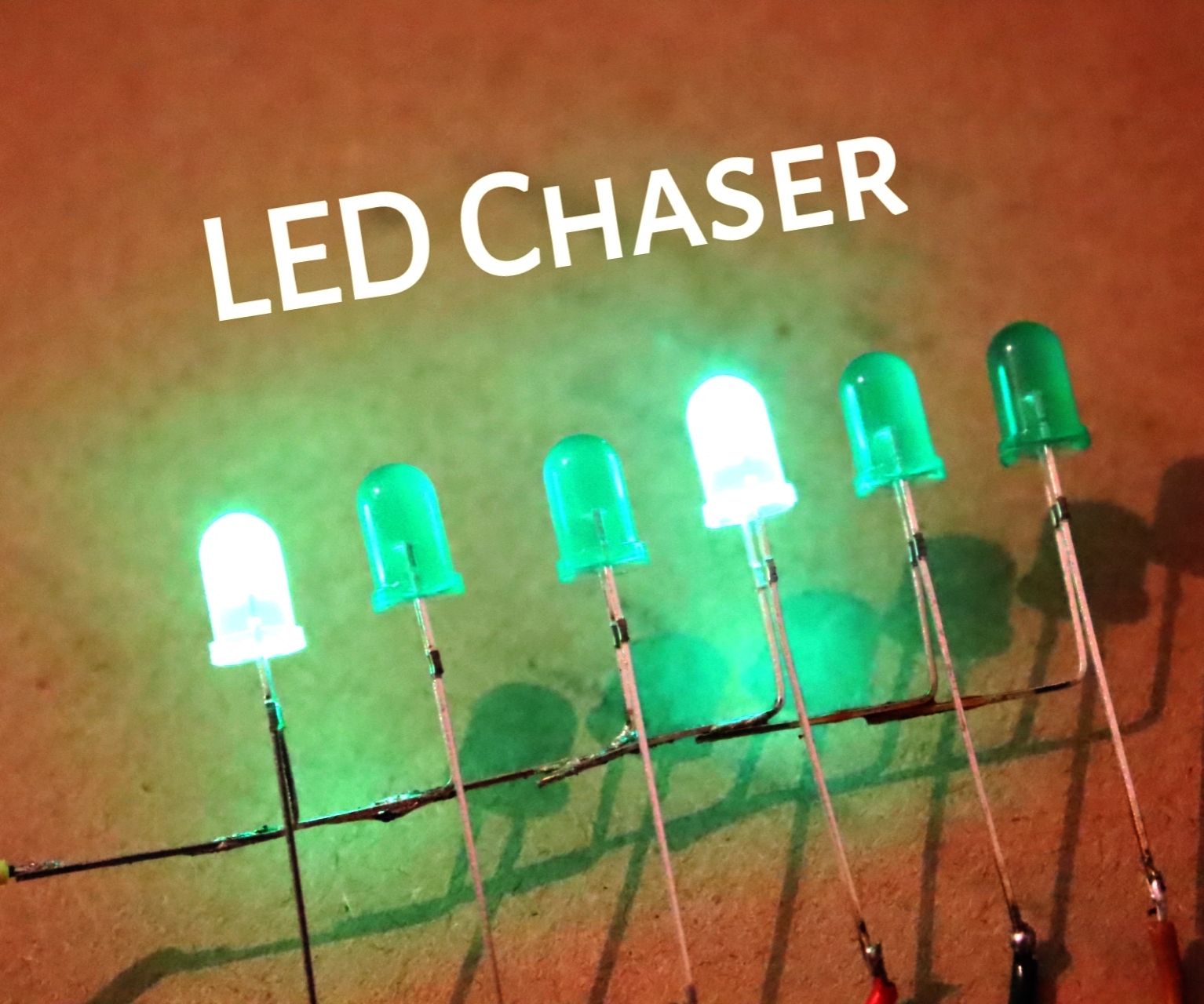
How to Make Best LED Chaser Circuit Without IC 15 Steps
K6JRF Auto Page
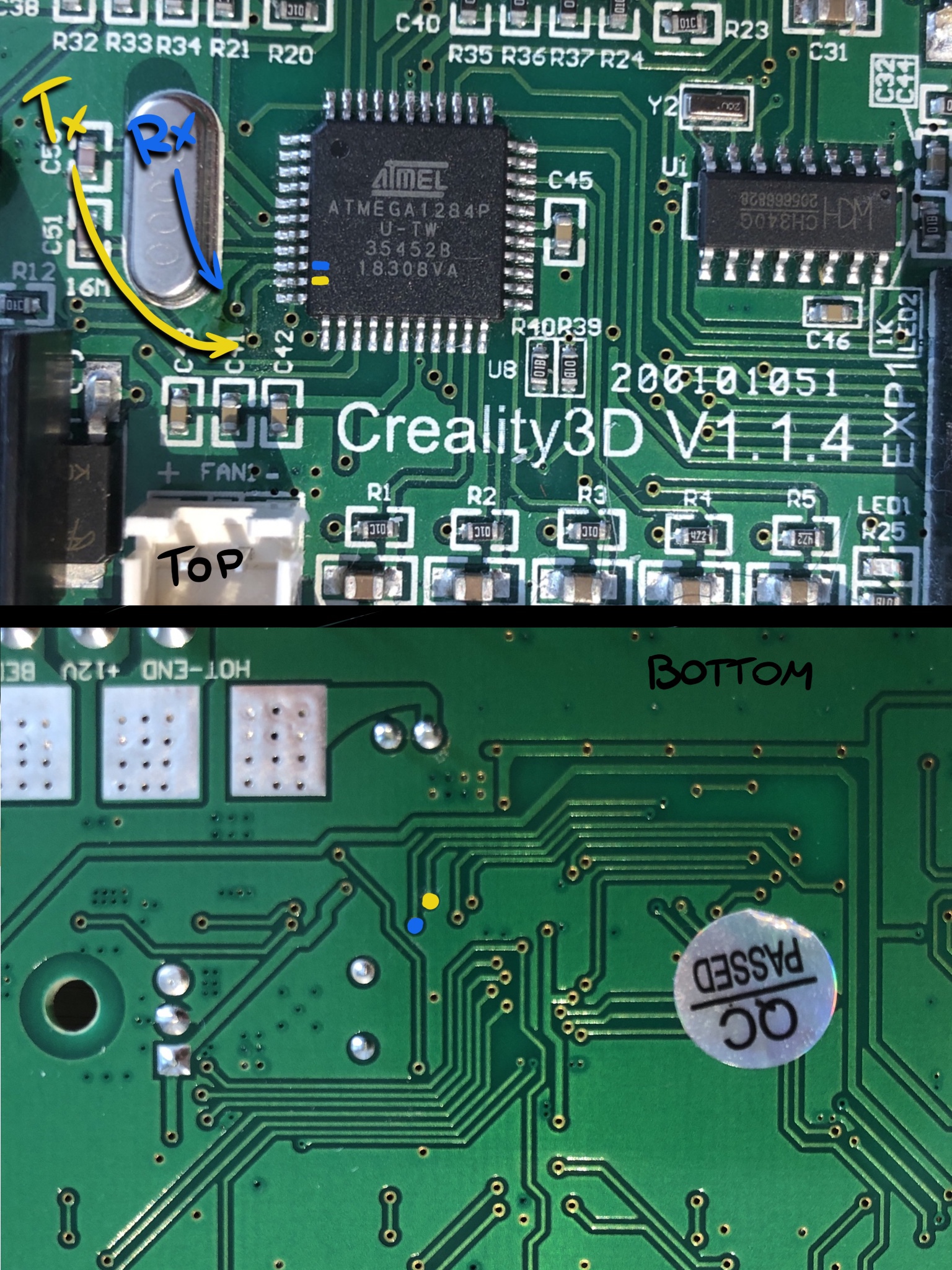
Connecting Ender3 to WiFi with ESP32