
 Skip to content


Void setup() { // put your setup code here, to run once: To interface the relay, it's best to use the negative side of the load and connect it to the relay normally open pin in series .

Create an Object Tracking System Part 2 Controlling a
The relays will be activated by a low signal.

How to wire a relay arduino. You can either run + to the (c)ommon on all the relays, and then connect the nc (or no, depending on which way you want it) to the positive side of the load (with negative side connected to ground), or do the reverse, grounding the common on the relays, and connecting the other relay terminal to the negative side of the load (withe the positive side of the load. We use the 5v output of the arduino for the power supply of the relay module. The other side has three low voltage pins (ground, vcc, and signal) which connect to the arduino.
The switching contacts of a relay are completely isolated from the coil, and hence from the arduino. There are leds on the board that show when a relay is active, and a green led to show that +5v power is applied. Although it may present a challenge to some, in most cases it’s just a matter of understanding the basic principles of a common relay.
Then the common ground of the relay is then connected to the ground line of your connection To control the relay module you can use any digital i/o pin of the arduino board. Digitally write to the pin :p.
Relay gnd > arduino gnd. How the 5v relay works. The 4 channel relay module has three high voltage terminals (nc, c, and no) which connect to the device you want to control.
I'm connecting the relay to analog pins on the arduino because in my circuit, i'm running low on digital pins. The following pictures show the wiring between the relay module and different arduino boards. We have connected transistor base to arduino pin a0 through a 1k resistor.
In this video you will get learn how to control an ac bulb or load or dc load using 5v relay. The connections between the relay module and the arduino are really simple: Here's my quick tutorial on how to hook up a relay to an arduino;
A relay accomplishes this by using the 5v outputted from an arduino pin to energize the electromagnet which in turn closes an internal, physical switch to turn on or off a higher power circuit. Note the arduino is being powered by the 5v usb power. The light bulb has one of the 120v wire spliced to connect the end connected to the power plug to the com (common) pin of the relay module and the one going to the lamp is connected to the nc (normally closed) pin.
You would connect arduino to the connector on the upper left. Controls the first relay (it will be connected to an arduino digital pin) in2: You can wire the relay outputs to various devices rated at up to 10 amps.
Controls the second relay (it should be connected to an arduino digital pin if you are using this second relay. +5v to vcc, four input pins, and gnd. Attach relay outputs as above.
You say, just under the image, to “connect the power wire of the light bulb cord to the no (normally open) terminal of the relay, and connect the neutral power wire of the cord to the c (common) terminal of the relay.” the image show the power wire is cut and the cut ends are then connected to the relay common and no intact. Analog pins on the arduino can be used as digital simply by setting the pinmode appropriately and using digitalwrite to. The 12v adaptor is used for powering the circuit.
It is a bridge between arduino and high voltage devices. It is used to programmatically control on/off the devices, which use the high voltage and/or high current. Attach arduino gpio pins to each chx pin.
Otherwise, you don’t need to connect it) The only link is by the magnetic field. Code is provided and controlling ac bulb is demonstrated.this v.
So for either board, connect the relay gnd to one of arduino's gnd pins and the relay 5v or arduino's 5v pin and the relay in to one of arduino digital outputs, say d4. In this arduino relay control circuit we have used arduino to control the relay via a bc547 transistor. } void loop() { // put your main code here, to run repeatedly:
The photo above shows this wiring. An ac bulb is used for demonstration. We connect the ir motion sensor “out” to pin 4 and the relay “in1″ to pin 8.
Then when the digital output, d4, is high the relay will operate.
Arduino IIC(I2C) LCD module 16×2
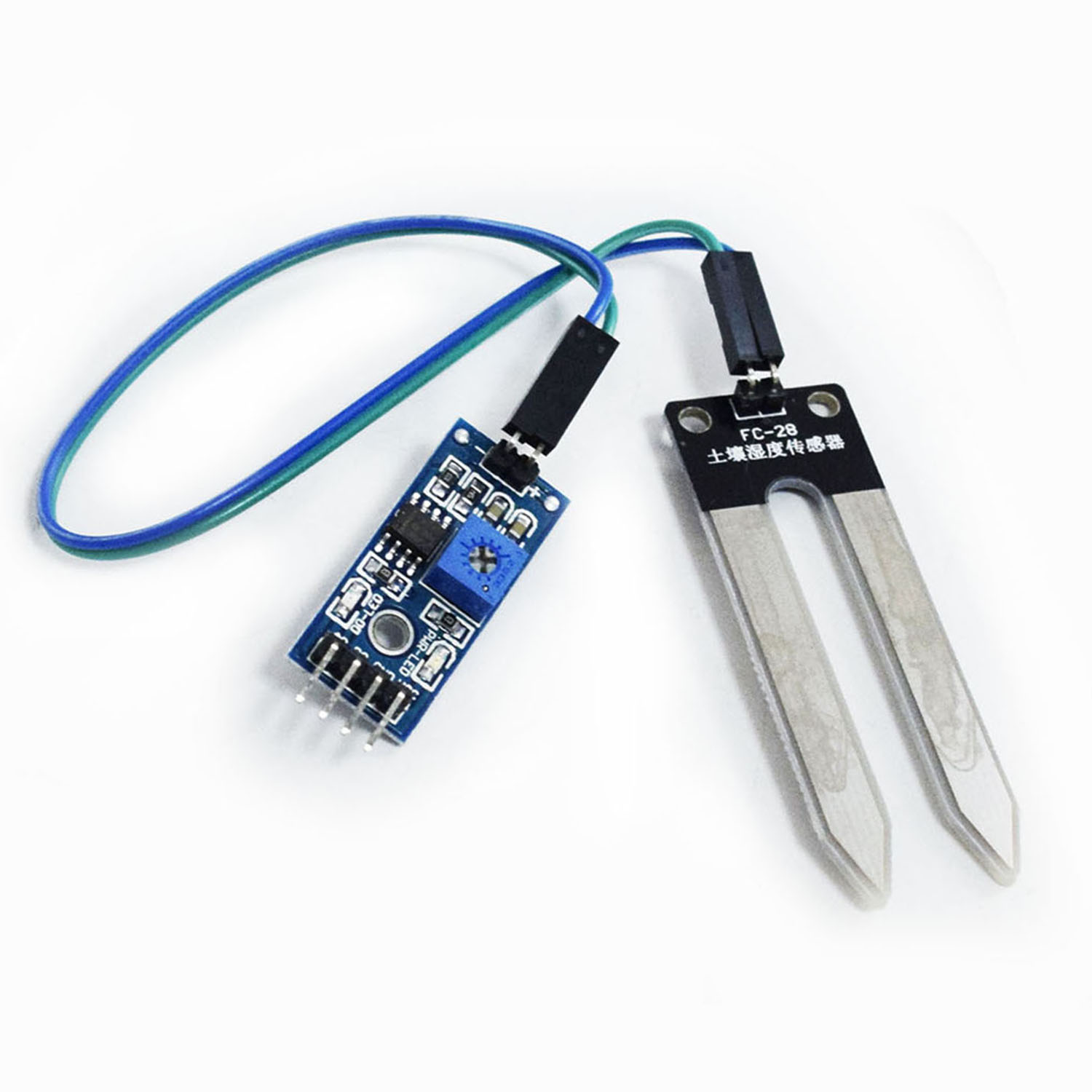
Soil Hygrometer Detection Module Soil Moisture Sensor For

Male to Female HQ jumper Wire Connector (10cm

4Channels L293D Motor Shield For Arduino Makerfabs


