Skip to content


Both types are diagrammed in accompanying illustrations. The breaker trips instantly when delta contact closes.

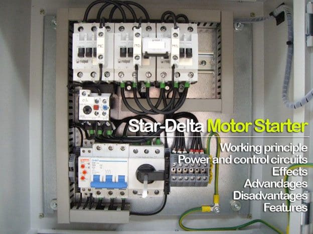
Star Delta Starter Motor Control with Circuit diagram
A sample wiring diagram is included as figure 9 on page 14.
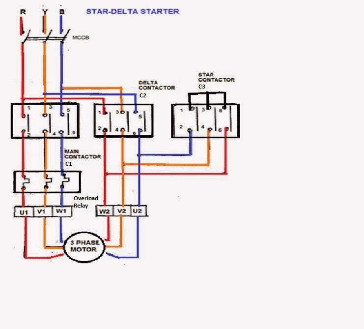
Wye delta starter circuit. The starter mainly consists of a tpdp switch which. A sample wiring diagram is included as figure 9 on page 14. A wiring diagram is a straightforward visual representation from the physical connections and physical layout associated with an electrical system or circuit.
They are used in an attempt to reduce the start current applied to the motor during start as a means of reducing the disturbances and interference on the electrical supply. You switch from wye to delta after 2.5 to 4 seconds, but the switch is instantaneous. When you make use of your finger or perhaps the actual circuit with your eyes, it is easy to mistrace the circuit.
The initial connection should be in the star pattern that results in a reduction of the line voltage by a factor of 1/√3 (57.7%) to the motor and the current is reduced. A time delay relay (timer) is in the control circuit. The initial connection should be in the star pattern that results in a reduction of the line voltage by a factor of 1/√3 (57.7%) to the motor and the current is reduced.
3 nos of fuse are used in series with the motor circuit to protect the motor from external over current and short circuit fault. A s tar delta starter is a type of reduced voltage starter. Closed transition starters do not permit this peak to occur.
A time delay relay (timer) is in the control circuit. When you make use of your finger or perhaps the actual circuit with your eyes, it is. When the start command is issued, contactor 1m is closed, connecting the motor in a wye configuration.
Wye/delta is used in high voltage transmission, and wye/wye is seldom used because of potential unbalance. I am aware of the wye delta transition inrush. Delta/delta is used in many industrial installations, while delta/wye is the most common configuration.
When the start command is issued, contactor 1m is closed, connecting the motor in a wye configuration. Figure 3 is the schematic for a delta/wye configuration. Initially at start the motor winding remains in the star configuration and after lapse of some time which is set time of timer the motor stator winding gets connected in the delta configuration.
The typical circuit includes three separate contactors, an overload relay, a timer, and an interlock. The primary is wound as delta, and the secondary is wound as wye. (known as wye/delta starters in the 60hz world).
We use it to reduce the starting current of the motor without using any external device or apparatus. Star/delta starters are probably the most common reduced voltage starters in the 50hz world. But this is an application where the wye delta starting arrangement has been successfully used many times with no problems.
This is a big advantage of a star delta starter, as it typically has around 1/3 of the inrush current compared to a dol starter. And this is happening to (2) identical installations of the air compressor and breakers, same location.
Stardelta motor starter explained in details EEP
Star Delta Starter Simple Circuit Diagram Sexy Fucking

Star delta starter Electrical Engineering Centre

WyeDelta Starting